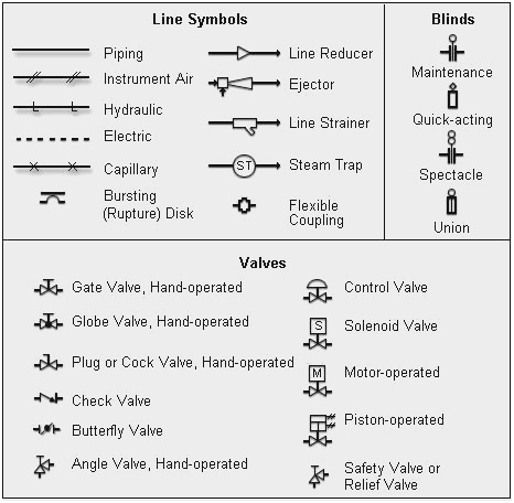
SolidPlant 3D is a database driven system and the piping specification assigned to the route will define the components created into the pipe line. I will outline how to create piping isometric drawings with SolidPlant 3D on top of SOLIDWORKS Standard Edition. This will eliminate the need to manually edit isometric drawings which significantly reduces fabrication and on-site construction errors. SolidPlant 3D has embedded Isogen® for the total automation of piping isometric drawings and is de facto standard CAD system for isos. Also includes pipe line details such as line number, revision number, dates, etc.Ĭreating piping isometric drawings is a huge task and time consuming effort with only SOLIDWORKS.


Main Graphic Section – A detailed orthographic representation that illustrates the details of 3D structure of the piping system in a single view.To accomplish this task, the piping isometric drawing consists of three sections that hold valuable info used by different project stakeholders at different times. The Isos bring clarity to contractors, construction crew and the overall project. It´s a three dimensional representation of a pipe line or part of it with all information necessary to purchase, fabricate, install and test the line or part of the line. For many decades Piping Isometric drawings have been used to represent a single pipe line in a plant, being the most important deliverable.


 0 kommentar(er)
